Views: 0 Author: Site Editor Publish Time: 2026-06-29 Origin: Site
In the complex and highly demanding world of modern fluid power systems, understanding the fundamental components that drive machinery is absolutely essential for engineers, maintenance professionals, and industrial operators. Among these critical components, the Hydraulic Hose stands out as a vital conduit that transmits energy, controls movement, and ensures the seamless operation of heavy-duty equipment across countless sectors. Whether deployed in massive construction excavators, intricate manufacturing assembly lines, or versatile mobile hydraulic systems, these flexible pipelines are tasked with containing and directing pressurized fluids safely and efficiently. To fully appreciate their capabilities, one must delve deeply into the intricate materials and sophisticated production processes that transform raw elastomers and steel into highly engineered fluid transmission solutions. This comprehensive exploration will illuminate the rigorous engineering principles, material science advancements, and manufacturing techniques required to produce hoses capable of withstanding extreme pressures, harsh environmental conditions, and continuous mechanical stress.
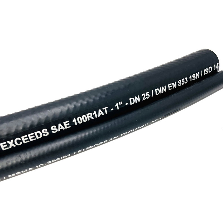
The multi-layered construction of a standard fluid transmission line, highlighting the inner tube, wire reinforcement, and protective outer cover.
To comprehend the manufacturing processes and material selections involved in creating a reliable fluid power conduit, it is first necessary to understand its basic structural anatomy. A standard industrial hose is not merely a simple rubber tube; it is a highly engineered, multi-layered composite structure designed to balance flexibility with immense structural integrity. The architecture generally consists of three primary components: the inner tube, the reinforcement layer, and the outer cover. Each of these layers serves a distinct and irreplaceable function, and the specific materials chosen for each layer dictate the overall performance, compatibility, and longevity of the final product.
The inner tube is the innermost layer that comes into direct contact with the hydraulic fluid. Its primary responsibility is to contain the fluid without degrading, swelling, or allowing permeation. The reinforcement layer surrounds the inner tube and provides the structural strength necessary to withstand the high internal pressures generated by fluid power systems. Without this critical layer, the inner tube would simply balloon and burst under pressure. Finally, the outer cover acts as the first line of defense against external environmental factors, protecting the delicate reinforcement layer from physical abrasion, chemical exposure, ultraviolet radiation, and extreme weather conditions. Together, these three layers form a cohesive unit that must perform flawlessly under continuous dynamic stress.
The inner tube is arguably the most chemically sensitive component of the entire assembly. Because it is in constant, direct contact with the transmission fluid—which can range from petroleum-based oils to water-glycol mixtures and synthetic lubricants—the material must exhibit exceptional chemical compatibility. In the case of the Grandflex DIN EN853 1SN / SAE 100R1AT product, the inner tube is meticulously crafted from an oil-resistant synthetic rubber. This specific material formulation is chosen for its ability to maintain structural integrity and dimensional stability even when exposed to aggressive petroleum-based hydraulic fluids at elevated temperatures.
If an incompatible material were used for the inner tube, the hydraulic fluid could cause the rubber to swell, soften, or become brittle. Swelling reduces the internal diameter of the passage, restricting fluid flow and causing pressure drops that negatively impact system efficiency. Brittleness, on the other hand, can lead to micro-cracking, which eventually allows pressurized fluid to seep into the reinforcement layer, compromising the entire structure. Therefore, the compounding of the synthetic rubber used in the inner tube is a highly specialized area of material science, requiring precise blends of polymers, plasticizers, and curing agents to achieve the perfect balance of flexibility, impermeability, and oil resistance.
While the inner tube contains the fluid, the reinforcement layer is what actually holds the pressure. The type, amount, and configuration of the reinforcement material directly determine the working pressure and burst pressure ratings of the assembly. For high-pressure hydraulic applications, high-tensile steel wire is the industry standard. The Grandflex DIN EN853 1SN / SAE 100R1AT utilizes a single braid of high-tensile steel wire for its reinforcement. This single-wire braid configuration provides an excellent balance between pressure containment and mechanical flexibility.
The steel wire used in these applications is not standard structural steel; it is specially drawn and treated to achieve extraordinary tensile strength. During the manufacturing process, multiple strands of this high-tensile wire are woven together in a precise crisscross pattern over the inner tube. This braided structure allows the assembly to expand slightly under pressure surges (acting as a shock absorber) while preventing catastrophic failure. The angle of the braid is a critical engineering parameter; it must be calculated perfectly to ensure that the hose neither elongates nor contracts excessively when pressurized. A single braid of high-tensile steel wire is particularly well-suited for industrial machinery and mobile hydraulic systems where a combination of high pressure and moderate flexibility is required.
The outer cover is the protective shield that ensures the longevity of the internal components. Even if the inner tube and reinforcement layer are perfectly engineered, the assembly will fail prematurely if the outer cover cannot withstand the operating environment. In industrial and construction settings, these components are routinely subjected to severe abrasion from rubbing against machinery chassis, exposure to harsh sunlight, and contamination from spilled oils, greases, and industrial chemicals.
To combat these environmental hazards, the Grandflex DIN EN853 1SN / SAE 100R1AT is equipped with a cover made from weather- and oil-resistant synthetic rubber. This specialized elastomer compound is formulated to resist degradation from ultraviolet (UV) light and ozone, which can cause standard rubber to crack and deteriorate over time. Furthermore, its oil-resistant properties ensure that accidental spills or leaks from adjacent machinery do not compromise the cover's structural integrity. By maintaining a robust barrier against external threats, the weather- and oil-resistant synthetic rubber cover protects the underlying high-tensile steel wire from rust and mechanical damage, thereby significantly extending the operational lifespan of the entire assembly.
The transformation of raw synthetic rubber and high-tensile steel wire into a finished, high-performance fluid transmission line is a complex, multi-stage manufacturing process. It requires state-of-the-art machinery, stringent quality control protocols, and precise environmental management. The production process can generally be divided into several key phases: compound preparation, inner tube extrusion, reinforcement application, outer cover extrusion, vulcanization, and final testing. Each step must be executed with exacting precision to ensure the final product meets rigorous international standards.
The manufacturing journey begins in the mixing department, where the raw materials for the synthetic rubber compounds are prepared. Raw elastomers are combined with various additives, including carbon black (for strength and UV resistance), plasticizers (for flexibility), antioxidants (to prevent aging), and curing agents (such as sulfur or peroxides). These ingredients are precisely weighed and fed into massive internal mixers, such as Banbury mixers, which use immense mechanical force and heat to blend the materials into a homogeneous compound. The resulting rubber mixture is then milled into continuous sheets or strips, ready to be fed into the extrusion machinery. Separate, distinct compounds are prepared for the oil-resistant inner tube and the weather-resistant outer cover, as their performance requirements differ significantly.
The first physical forming step is the creation of the inner tube. This is accomplished using a specialized machine called an extruder. The prepared synthetic rubber compound is fed into the extruder, where a rotating screw forces the material through a heated barrel. The heat and pressure soften the rubber, making it pliable. At the end of the barrel, the rubber is forced through a precision-machined die and a central mandrel. The mandrel determines the internal diameter of the tube, while the die determines the outer diameter and wall thickness.
For the Grandflex DIN EN853 1SN / SAE 100R1AT, this extrusion process must be tightly controlled to produce inner tubes that will eventually accommodate metric sizes ranging from 5.0 mm to 51.0 mm (equivalent to 3/16 inch to 2 inch). As the hot, unvulcanized rubber tube exits the extruder, it is typically cooled in a water bath to stabilize its dimensions. At this stage, the rubber is still relatively soft and uncured, meaning it must be handled with care to prevent deformation before the reinforcement layer is applied.
Once the inner tube has been extruded and stabilized, it moves to the braiding department. This is where the critical high-tensile steel wire is applied. The inner tube is passed through the center of a massive braiding machine, which consists of multiple carriers holding spools of fine steel wire. These carriers move in complex, intersecting circular paths, weaving the wire strands over the surface of the inner tube in a precise, continuous pattern.
For a product featuring a single braid of high-tensile steel wire, the machine is calibrated to lay down the wire at a specific angle—typically around 54 degrees, 44 minutes, known as the neutral angle. Braiding at this exact angle ensures that when the assembly is subjected to internal pressure, the forces attempting to expand the diameter and the forces attempting to elongate the structure are perfectly balanced, resulting in minimal dimensional change. The tension of each individual wire must be strictly monitored during this process; if the tension is uneven, the resulting braid will be compromised, leading to weak spots and potential burst failures in the field.
With the steel wire reinforcement securely in place, the semi-finished assembly is routed to a second extrusion line for the application of the outer cover. The process is similar to the inner tube extrusion, but the die is sized to accommodate the larger diameter of the reinforced structure. The weather- and oil-resistant synthetic rubber compound is heated and forced over the wire braid, creating a seamless, protective outer jacket.
During this stage, it is crucial to achieve excellent adhesion between the outer cover and the steel wire reinforcement. In some manufacturing processes, a thin layer of adhesive or a specialized bonding agent is applied over the wire braid before the outer cover is extruded. This ensures that the layers do not delaminate or separate when the assembly is subjected to severe bending or mechanical stress during operation. The thickness of the outer cover is also carefully controlled to provide adequate protection without adding unnecessary weight or stiffness.
At this point in the production process, the assembly has its final shape and structure, but the synthetic rubber is still uncured. To achieve its final physical properties—such as elasticity, tensile strength, and resistance to heat and chemicals—the rubber must undergo vulcanization. Vulcanization is a chemical process that cross-links the polymer chains within the rubber, transforming it from a soft, tacky substance into a durable, resilient elastomer.
The unvulcanized assemblies are typically wrapped tightly in a nylon or lead tape to maintain their shape and consolidate the layers, and then placed into massive industrial autoclaves. High-pressure steam is introduced into the autoclave, subjecting the products to precise temperatures and pressures for a specified duration. The heat triggers the chemical curing agents within the rubber compounds, causing the cross-linking reaction to occur. Once the vulcanization cycle is complete, the assemblies are removed from the autoclave, and the wrapping tape is stripped away, leaving behind the characteristic textured finish often seen on industrial fluid transmission lines.
The rigorous materials and production processes described above are designed to produce a product that meets exact engineering specifications. Understanding these specifications is critical for selecting the correct component for a given application. The Grandflex DIN EN853 1SN / SAE 100R1AT serves as an excellent case study for analyzing these vital performance metrics.
Size is the most fundamental specification. The internal diameter determines the volume and velocity of fluid that can be transmitted. The Grandflex product is available in a wide range of metric sizes, specifically from 5.0 mm to 51.0 mm, which corresponds to imperial sizes from 3/16 inch to 2 inch. This broad size range ensures that engineers can select the appropriate diameter to minimize pressure drops and prevent excessive fluid velocity, which can cause heat generation and system inefficiency.
Pressure ratings are the ultimate test of the reinforcement layer's integrity. There are two primary pressure metrics to consider: working pressure and burst pressure. Working pressure is the maximum continuous pressure the system should operate under during normal conditions. For the Grandflex DIN EN853 1SN / SAE 100R1AT, the working pressure ranges from 4.0 Mpa to 25.0 Mpa (equivalent to 580 Psi to 3625 Psi), depending on the specific size of the assembly. Smaller diameters generally handle higher pressures than larger diameters due to the physics of hoop stress.
Burst pressure is a safety metric; it represents the absolute minimum pressure at which a catastrophic failure (rupture) is expected to occur in a laboratory setting. Industry standards typically require the burst pressure to be at least four times the maximum working pressure, providing a 4:1 safety factor. The burst pressure for this specific Grandflex product ranges impressively from 16 Mpa to 100 Mpa, depending on size, ensuring a robust safety margin against unexpected pressure spikes or hydraulic shock.
In mobile hydraulic systems and compact industrial machinery, flexibility and weight are critical considerations. The bending radius indicates the tightest curve the assembly can be bent into without kinking, damaging the wire reinforcement, or restricting fluid flow. The Grandflex product offers a bending radius that ranges from 90 mm to 630 mm, depending on the size. This flexibility allows for easier routing through tight engine compartments and complex mechanical linkages.
Weight is also a factor, particularly in mobile equipment where overall vehicle weight impacts fuel efficiency and performance. Due to its efficient single-wire braid construction, the weight of this product ranges from 0.20 Kg/m to 2.00 Kg/m, depending on size. This provides a relatively lightweight solution without sacrificing the necessary pressure containment capabilities.
Because fluid power systems operate under extreme pressures, safety and reliability are paramount. To ensure consistency and safety across the global market, international standards organizations have established rigorous testing and performance criteria. A high-quality product must be manufactured to meet or exceed these established standards.
The Grandflex DIN EN853 1SN / SAE 100R1AT is engineered to be fully compliant with several critical industry benchmarks. It meets the requirements of the SAE 100R1AT standard, which is established by the Society of Automotive Engineers and dictates the dimensions, performance, and testing procedures for single-wire braid reinforced products. Furthermore, it complies with the EN853 1SN standard, a European norm that specifies similar rigorous criteria. In addition to these primary designations, the product also meets ISO 1436 and SAE J517 specifications, ensuring global compatibility and providing engineers with the confidence that the component will perform reliably in demanding environments.
The specific combination of an oil-resistant inner tube, a single braid of high-tensile steel wire, and a weather- and oil-resistant synthetic rubber cover makes this type of product incredibly versatile. Its robust construction allows it to be deployed across a wide spectrum of demanding industries.
One of the primary use cases is in high-pressure hydraulic applications, where reliable fluid transmission is non-negotiable. In the realm of industrial machinery, these components are used to power presses, injection molding machines, and automated assembly equipment, providing the precise force required for heavy manufacturing. Construction equipment, such as excavators, loaders, and cranes, rely heavily on these robust lines to actuate massive cylinders and motors under harsh, abrasive conditions. Additionally, they are essential in mobile hydraulic systems found in agricultural tractors, forestry equipment, and municipal utility vehicles, where flexibility, durability, and resistance to environmental exposure are absolutely critical for daily operations.
The Grandflex DIN EN853 1SN / SAE 100R1AT represents a highly engineered solution for demanding fluid power transmission, combining an oil-resistant synthetic rubber inner tube, a robust single braid of high-tensile steel wire, and a durable weather- and oil-resistant cover to deliver reliable performance across industrial machinery, construction equipment, and mobile hydraulic systems. With its broad range of metric sizes (5.0 mm to 51.0 mm), impressive working pressures (4.0 Mpa to 25.0 Mpa), and strict compliance with SAE 100R1AT, EN853 1SN, ISO 1436, and SAE J517 standards, this product offers engineers and maintenance professionals a versatile, high-quality component perfectly suited for safe and efficient high-pressure hydraulic applications.