Views: 188 Author: Site Editor Publish Time: 2026-09-09 Origin: Site
Selecting the correct hydraulic hose size determines whether fluid systems deliver optimal power or suffer from pressure drops, excessive heat, and premature fitting blowouts. Mechanics, hydraulic engineers, and procurement teams often struggle to convert Dash sizes, Inner Diameter (ID), Outer Diameter (OD), and Nominal Diameter (DN).
A clear Hydraulic Hose Size Chart: Dash Size, ID, OD and DN Explained eliminates guesswork during maintenance and system design. Misinterpreting these sizing parameters causes restricted fluid flow, excessive pressure drop, tube erosion, or choosing mismatched crimp fittings that leak under pressure.
Below is a complete sizing guide and conversion chart for every standard hydraulic hose size, breaking down Dash numbers, exact dimensions, flow velocity considerations, and manufacturing standards.
Understanding the relationships between Dash sizes, metric dimensions, and fractional inch measurements makes ordering replacement lines simple. This master reference table covers the most common standard industrial hydraulic hose dimensions used globally across SAE J517 and ISO standards.
Dash Size (-16ths) | Inner Diameter (ID) Inches | Inner Diameter (ID) mm | Outer Diameter (OD) Approx. mm | Nominal Diameter (DN) | Standard Industrial Flow Range (GPM)* |
-02 | 1/8" | 3.2 mm | 8.7 mm | DN 04 | 0.5 – 1.5 GPM |
-03 | 3/16" | 4.8 mm | 11.8 mm | DN 05 | 1.0 – 3.0 GPM |
-04 | 1/4" | 6.4 mm | 13.4 mm | DN 06 | 2.0 – 6.0 GPM |
-05 | 5/16" | 7.9 mm | 15.0 mm | DN 08 | 3.5 – 9.0 GPM |
-06 | 3/8" | 9.5 mm | 17.4 mm | DN 10 | 5.0 – 15.0 GPM |
-08 | 1/2" | 12.7 mm | 20.6 mm | DN 12 | 8.0 – 25.0 GPM |
-10 | 5/8" | 15.9 mm | 23.8 mm | DN 16 | 15.0 – 40.0 GPM |
-12 | 3/4" | 19.0 mm | 27.8 mm | DN 20 | 25.0 – 60.0 GPM |
-16 | 1" | 25.4 mm | 35.6 mm | DN 25 | 40.0 – 100.0 GPM |
-20 | 1-1/4" | 31.8 mm | 43.5 mm | DN 32 | 65.0 – 160.0 GPM |
-24 | 1-1/2" | 38.1 mm | 50.8 mm | DN 40 | 90.0 – 225.0 GPM |
-32 | 2" | 50.8 mm | 63.5 mm | DN 50 | 160.0 – 400.0 GPM |
(Note: Outer Diameter measurements vary slightly depending on wire braid vs. spiral steel reinforcement structures. Always check manufacturer datasheets for exact OD tolerances.)
Dash Size Increment: Each Dash number increment represents 1/16th of an inch of the inner diameter (except for dedicated automotive power steering lines).
Metric Equivalents: European and Asian equipment commonly labels lines using DN (Diameter Nominal) numbers based on approximate metric IDs.
Flow Rates: Matching flow velocity to tube ID prevents fluid turbulence, fluid overheating, and internal tube erosion.
Dash size numbers serve as the global fluid power industry standard for specifying line dimensions quickly without writing fractions.
Dash Size Conversion Formula:
[ Dash Number ]  ÷  16  =  [ Inner Diameter in Inches ]

Example (-08 Dash):
8  ÷  16  =  8/16"  =  1/2" ID
The Dash size system expresses the inner tube diameter in sixteenths of an inch. A dash sign precedes the number (e.g., -06).
-04 Dash Size: Equals 4/16" inner diameter, which simplifies to 1/4" (6.4 mm).
-08 Dash Size: Equals 8/16" inner diameter, which simplifies to 1/2" (12.7 mm).
-12 Dash Size: Equals 12/16" inner diameter, which simplifies to 3/4" (19.0 mm).
-16 Dash Size: Equals 16/16" inner diameter, which simplifies to 1" (25.4 mm).
A few exceptions exist within specialized mobile and automotive applications:
SAE J518 Flange Fittings: Flange sizes use dash numbers corresponding to port sizes rather than hose IDs.
Hard Brake & Steering Lines: Automotive rigid tubing dash sizes sometimes refer to Outer Diameter (OD) rather than Inner Diameter (ID).
Accurately measuring a flexible hydraulic hose requires measuring both the inner opening and the outer protective cover. Confusing ID with OD leads to sizing errors during replacement.
Inner Diameter represents the span across the internal rubber lining layer.
Flow Rate Control: ID dictates the volumetric flow rate (GPM or L/min) and fluid velocity through your system.
Sizing Accuracy: Replacing a line with a smaller ID restricts flow, causing backpressure, elevated system temperatures, and efficiency loss.
Fitting Selection: The hose end fitting insert stem must fit the internal diameter precisely to ensure a leak-free mechanical seal.
Outer Diameter measures the entire cross-section, including the inner tube, steel wire reinforcement layers, and outer rubber cover.
Routing Constraints: OD determines whether the line fits inside protective spring guards, mounting clamps, structural frame cutouts, and tight engine bays.
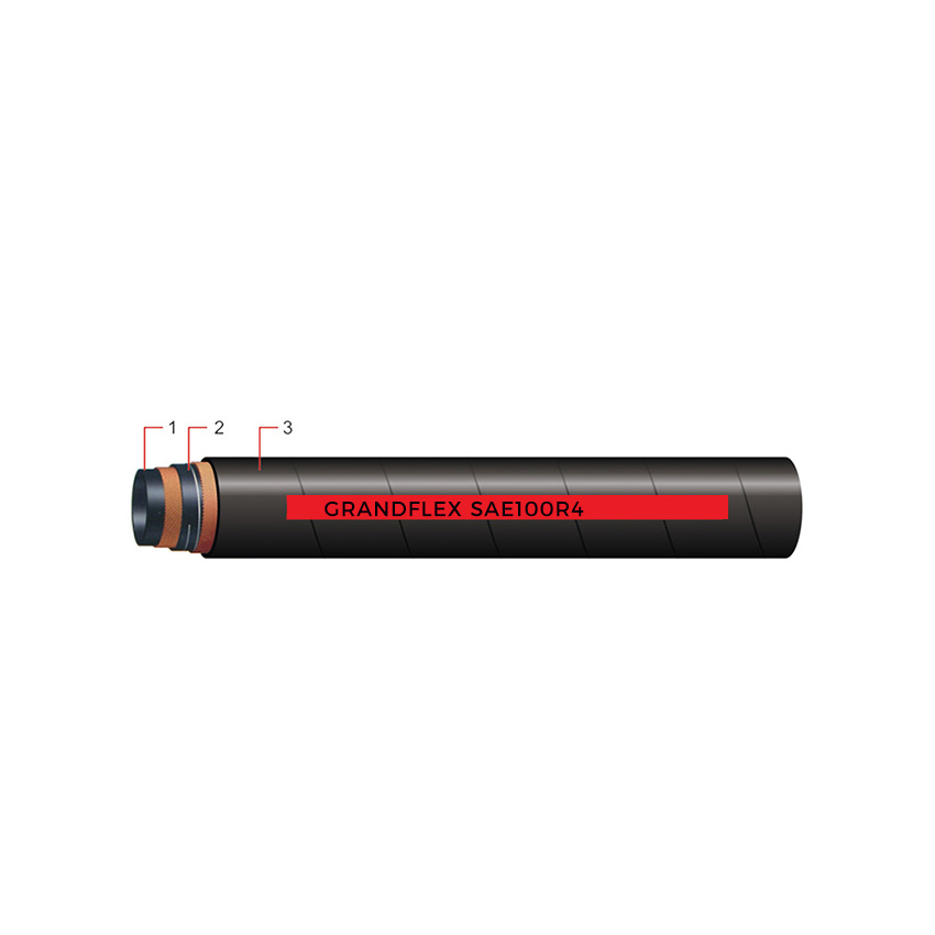
Die Selection: Crimp die selection depends directly on the outer diameter. Two lines with identical 1/2" IDs can have different ODs depending on whether they use single-wire braid (SAE 100R1) or four-wire spiral steel construction (SAE 100R4/R12).
European and Asian equipment manufacturers specify fluid lines using Nominal Diameter (DN) designations based on metric standards (ISO 6708 / DIN EN 853).
DN stands for Diamètre Nominal (Nominal Diameter). It is an international metric shorthand rounded to the nearest standardized millimeter equivalent of the internal diameter.
DN 06: Equivalent to 1/4" ID (-04 Dash).
DN 12: Equivalent to 1/2" ID (-08 Dash).
DN 25: Equivalent to 1" ID (-16 Dash).
DN 50: Equivalent to 2" ID (-32 Dash).
When servicing imported machinery, technicians must match metric DN ratings to imperial Dash sizes to avoid installation delays.
Metric & Imperial Cross-Reference Path:
[ DN Metric Designation ] ──► [ Nearest mm ID ] ──► [ Fractional Inch ] ──► [ Dash Size ]

Example:
DN 16  ──►  15.9 mm ID  ──►  5/8 Inch ID  ──►  -10 Dash Size
Connecting a metric DN line to an imperial fitting works seamlessly as long as the internal stem matches the hose ID and the crimp die specs match the outer wall thickness.
When replacing a damaged heavy-duty hydraulic hose on a jobsite, relying on printed sidewall laylines is ideal. However, when layline text wears off, taking precise manual measurements becomes necessary.
Step 1: Cut the Line Squarely
Ensure you cut the hose end completely flat at a 90-degree angle. Angle cuts distort diameter readings.
Step 2: Measure Inner Diameter (ID) with Calipers
Insert the internal jaws of a digital vernier caliper into the inner tube lining. Take two readings 90 degrees apart to account for minor oval distortion and calculate the average.
Step 3: Measure Outer Diameter (OD)
Close the external caliper jaws around the outer rubber cover. Measure at an un-crimped, un-damaged section along the length.
Step 4: Check the Sidewall Layline
Read the factory layline text printed along the outer wall. It typically lists the manufacturer name, part number, inner diameter, dash size, pressure rating, and production batch date (e.g., 2-WIRE BRAID 1/2" (DN12) -08 WP 275 BAR / 3980 PSI).
Selecting an improper hydraulic hose line size impacts overall hydraulic power transmission efficiency. Hose ID directly influences fluid velocity and pressure stability.
Fluid flow velocity follows the principle of continuity ($Q = A \times v$). When fluid passes through a smaller tube cross-section at a constant flow rate, velocity increases dramatically.
Under-Sized Hose (Too Small ID):
Causes turbulent fluid flow and high friction loss along internal walls.
Generates excessive heat, accelerating rubber seal and fluid degradation.
Drops working pressure at hydraulic actuators, reducing equipment speed and power output.
Over-Sized Hose (Too Large ID):
Increases line weight, minimum bend radius requirements, and component costs.
Creates routing difficulties in tight machinery spaces.
Increases total fluid volume requirements in large systems.
Pressure Lines (Pump Outflow): 10 to 25 feet/sec (3.0 to 7.6 m/s).
Return Lines (Tank Return): 5 to 10 feet/sec (1.5 to 3.0 m/s).
Suction Lines (Pump Inlet): 2 to 5 feet/sec (0.6 to 1.5 m/s).
As an established fluid conveyance manufacturer, Qingdao Grantseed Rubber Co., Ltd. produces high-performance industrial lines for global OEM and distribution partners. Operating under ISO 9001:2008 quality management systems, our modern manufacturing facilities deliver precision-engineered hydraulic hose assemblies that meet demanding working environments.
Strict SAE & DIN Compliance: We manufacture high-pressure wire-braided and spiral steel wire lines in full compliance with SAE J517 (100R1AT, 100R2AT, 100R12, 100R13, 100R15) and DIN EN 853 / EN 856 standards.
Extensive Size Coverage: Our production spans from -04 (1/4") up to -32 (2") sizes across all major pressure ratings, ensuring exact Dash, ID, and DN tolerances.
Comprehensive Testing & OEM Services: We perform rigorous impulse, burst, and dimensional tolerance testing on every batch. We also provide custom branding, private label layout printing, cut lengths, and specialized abrasion-resistant covers for mining, agricultural, and construction machinery.
Our engineering team assists global clients in selecting certified, leak-free fluid line solutions tailored to their exact operating demands.
Mastering a Hydraulic Hose Size Chart: Dash Size, ID, OD and DN Explained allows maintenance teams and engineers to specify fluid lines with confidence. Matching Dash numbers to exact inner diameters, outer wall tolerances, and DN ratings prevents pressure losses, premature wear, and installation delays.
Taking accurate caliper measurements and sizing lines for recommended fluid velocities ensures your machinery operates at peak efficiency with minimal downtime.
Dash size -08 indicates an internal diameter of 8/16 of an inch, which simplifies to 1/2 inch (or approximately 12.7 mm / DN 12).
A hydraulic hose size is always classified by its Inner Diameter (ID) to ensure correct fluid flow capacity. Outer Diameter (OD) is measured separately to select correct crimp dies, protective guards, and mounting clamps.
Outer diameter varies based on reinforcement construction. A double wire braid line (SAE 100R2) or four-wire spiral line (SAE 100R12) has thicker reinforcement layers and outer covers than a single wire braid line (SAE 100R1), resulting in a larger OD despite having the same ID.
Yes, DN 12 is the metric nominal diameter equivalent to a 1/2 inch (-08 dash) line. Both share an internal diameter of approximately 12.7 mm.